Integrating BIM/CAD with GIS: Lessons Learned and Best Practices
Bridging the gap between CAD or BIM and GIS technologies is essential for enabling design professionals and GIS analysts to seamlessly share their data, but it is not without its challenges. This blog post explores some of the key obstacles, with a particular focus on georeferencing, and offers solutions to streamline the process.
In the ever-evolving landscape of geospatial technology, the integration of CAD (Computer-Aided Design) or BIM (Building Information Model) into GIS (Geographic Information Systems) is becoming increasingly important. CAD or BIM software, known for its precision and detailed design capabilities, is widely used in engineering, architecture, and construction (AEC). GIS software, in contrast, excels in analyzing and visualizing spatial data for decision-making in fields such as urban planning, environmental management, and transportation. Overcoming the challenges inherent to combining data from two different but complementary systems can lead to improved analysis and decision-making.
The Challenges of CAD to GIS Integration
Georeferencing Issues
One of the most significant challenges in integrating CAD and BIM into GIS is georeferencing or projection. Unlike GIS datasets, CAD or BIM files often lack spatial reference information. This means that while CAD and BIM drawings are precise within their local coordinate system, they don’t inherently align with real-world geographic locations. For example, an architectural blueprint of a building might use an arbitrary origin point. This lack of geospatial context can hinder the ability to overlay CAD data with other GIS layers, such as land parcels, road networks, or environmental features. Georeferencing CAD or BIM data involves applying a conformal transformation, which relies heavily on the accuracy of selected ground control points (GCP). These control points can be derived manually from orthoimagery basemaps or collected during field operations.
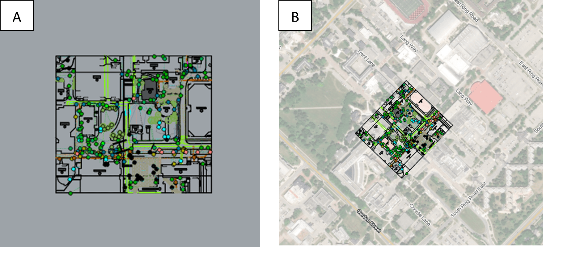
CAD data imported to GIS environment A) before the georeferencing process, B) after the georeferencing process
Data Conversion
Another major challenge is converting data from standard CAD formats, such as DWG and DXF, into a GIS-compatible format. During conversion, there is often a loss of geometric precision or attribute data. For instance, detailed shapes like arcs and curves in CAD may be simplified into straight-line segments in GIS, reducing data fidelity. Additionally, attribute data may not transfer seamlessly, leading to incomplete or incorrect GIS datasets. This challenge highlights the need for specialized tools and workflows to ensure accurate and useful GIS data.
In addition, integrating CAD/BIM data into GIS presents significant challenges due to the inherent differences in data structures and formats. CAD and BIM systems are designed for precision in engineering and architectural designs, often utilizing different classes and schemas tailored to their specific applications. In contrast, GIS emphasizes spatial analysis, requiring a geometry and location-based structure to manage the datasets. Converting data between these systems often involves resolving mismatched classes, attributes, and geometries, which can result in data loss or misinterpretation if not handled carefully.
Complex Layer Structures
CAD or BIM files often contain complex layer structures, where each layer can represent different components such as buildings, utilities, roads, or annotations. These layers are essential for organizing and managing the various elements within a design. However, several challenges can arise when converting these CAD layers into GIS datasets. One potential challenge is due to the organization of the layers. If the layers are not well-structured or logically grouped, it can be difficult to identify and separate the different elements accurately. This can lead to errors or inconsistencies in the GIS data.
Another potential issue is a lack of descriptive metadata. Metadata provides important information about the data, such as its source, accuracy, and purpose. If the CAD layers do not have detailed metadata, it can be challenging to understand the context and significance of each layer, making the translation process more complex. Additionally, CAD files may use different conventions and standards compared to GIS systems. This can result in compatibility issues, requiring additional steps to ensure that the data is correctly interpreted and integrated into the GIS environment.
Solutions and Best Practices
Georeferencing CAD Data
To address georeferencing issues, start by identifying or defining a spatial reference system for your CAD or BIM file. ArcGIS offers georeferencing tools that allow you to align CAD and BIM drawings with known geographic coordinates. This process typically involves:
-
- Identifying control points in the CAD file and matching them with corresponding points in a GIS dataset.
- Applying a transformation to align the CAD data with the chosen coordinate system.
 ArcGIS Pro Georeferencing toolbar
In ArcGIS Pro, the georeferencing tool enables users to manually georeferenced a CAD drawing with their corresponding ground locations or known coordinates. After defining the right projection in ArcGIS Pro, at least two points from the drawing and the corresponding ground locations are selected and matched. Then, the tool calculates a conformal transformation matrix to accurately align the CAD data with the GIS coordinate system. The resulting transformation parameters and the projection file are stored in .wld3 and .prj files, which are saved in the same directory as the CAD file. These .wld3 and .prj files can serve as a universal transformation for other CAD and BIM files, provided they share the same local coordinate system. This blog post by David Kossowsky highlights best practices for integrating BIM models into GIS and georeferencing them within ArcGIS Pro.
![]()
WLD3 transformation file example
Users also have the option to manually supply the transformation matrix values in a text file, which ArcGIS Pro can automatically use to project the CAD and BIM data within the GIS environment. This approach is particularly useful when the transformation matrix has already been calculated externally or when a consistent transformation needs to be applied across multiple CAD or BIM files.
Data Cleaning and Preparation
Before importing CAD data into a GIS, it’s important to clean up the CAD file by removing unnecessary elements like text annotations and construction lines, simplifying complex geometries to ensure compatibility with GIS software, organizing layers with meaningful names for easier identification and management, checking for consistency in data formats and attributes, and adding metadata to provide context and information about the data. These steps help ensure a smooth and accurate conversion process, maintaining data integrity and usability in the GIS environment.
Conversion Tools
When converting CAD data into GIS-compatible formats, use specialized tools that have been designed for the task. Software such as Safe Software’s FME or the Data Interoperability extension in ArcGIS Pro can streamline the conversion process while maintaining both attributes and geometry. Additionally, exporting CAD data to formats like shapefiles (SHP) or GeoJSON can improve compatibility with GIS workflows.
Recently, Esri and Autodesk formed a strategic partnership to address the longstanding challenges of integrating CAD and GIS workflows. This collaboration aims to bridge the gap between Autodesk's design and engineering tools, such as AutoCAD, Revit and Civil 3D, and Esri's powerful GIS platform, ArcGIS. Through this partnership, users can now more easily import and export CAD files into GIS environments, streamlining the exchange of data between the two systems. This another blog post by David Kossowsky showcases the work of students in the Building Information Modeling Management Program at George Brown College, who collaborated with Esri Canada Education and Research to explore BIM and CAD integration within ArcGIS Pro. This integration is made more seamless through the ongoing collaboration between Autodesk and Esri.
In addition, the ArcGIS Data Interoperability extension for ArcGIS Pro, powered by Safe Software's FME technology, plays a key role by providing an integrated ETL toolset to handle diverse data formats including CAD files. Users can utilize FME Workbench to create custom workflows for automating data extraction and transformation. In the future, I plan to explore the functionalities of the ArcGIS Data Interoperability extension for ArcGIS Pro, focusing on data export, transformation, and loading (ETL) into geodatabases.
Future Trends in CAD-GIS Integration
The integration of Building Information Modeling (BIM) with GIS is revolutionizing how design and spatial data are combined, bridging the gap between BIM and GIS. Tools like Autodesk InfraWorks and Esri’s ArcGIS GeoBIM enable seamless collaboration, while the partnership between Autodesk and Esri simplifies data exchange, preserving attributes like geometry and metadata.
Recent advancements in toolsets and collaborative data exchange between developers have effectively addressed many of the issues with data integration, making integration more feasible and efficient. Future advancements, such as AI and machine learning, are further streamlining processes like georeferencing and data cleaning, making workflows more efficient and accurate. These innovations are transforming CAD-to-GIS integration into a more automated and collaborative ecosystem.
One of the key outcomes of this advancement in data integration is improved data interoperability, enabling design professionals and GIS analysts to seamlessly share and visualize CAD models within ArcGIS while preserving essential attributes like geometry, layers, and metadata. Furthermore, GIS users can enhance CAD designs with spatial analysis and geographic context, which are critical for tasks like urban planning, infrastructure development, and environmental assessments. By bridge the gap between these two technologies, professionals can unlock new possibilities for spatial analysis and decision-making. Whether you’re planning urban infrastructure or managing environmental resources, the successful integration of CAD and GIS can lead to more informed and impactful outcomes.